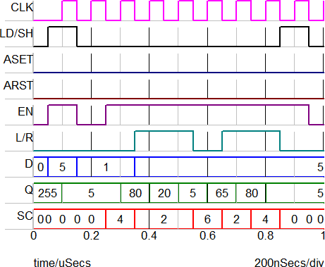
8 Bit Barrel Shifter Truth Table
More Combinational Circuits
Shifter Barrel
Barrel Shifter 8 Bit
58 What Is Sarbanes Oxley Q
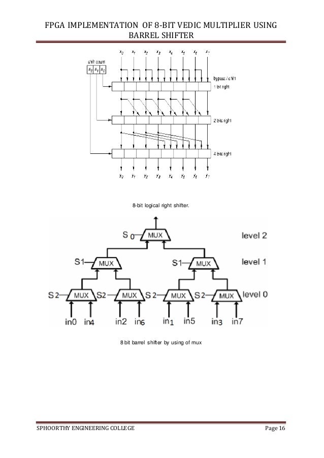
Fpga Implementation Of High Speed 8 Bit Vedic Multiplier Using Barrel
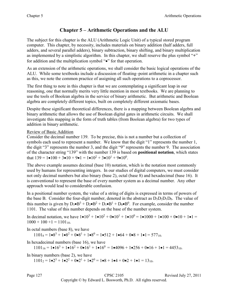
Arithmetic Operators And The Alu
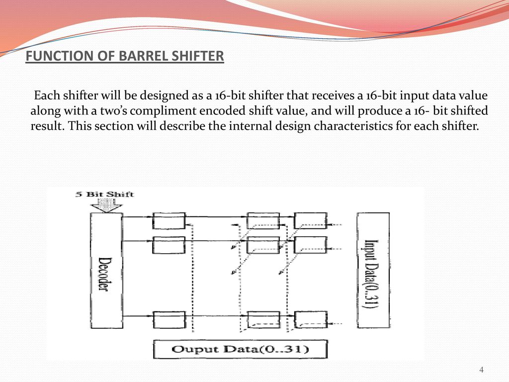
In this VHDL project, a shifter with the ability to shift and rotate data, which is mainly used in the permutation and transpositions of ciphers, will be implemented in VHDLThe VHDL shifter is a key component in the upcoming coprocessor's processing unit Fast shifting and rotating functions are critical for cryptographic applications VHDL code for the shifter will be presented together.

8 bit barrel shifter truth table. Two 16bit barrel shifters are implemented in a 5V 06 m CMOS technology one in normal Domino logic and the other in our proposed 3 Separate power leads are used on the chip to measure power consumption of separate sections Postlayout simulations show that, depending on input patterns, a 3 shifter consumes 8% to 62%. Required is n log2(n) where n is the number of bits supported So for an 8bit barrel shifter the calculation is 8 × log2(8) = 8 × 3 = 24 12 Pulsed latches Pulsedlatch circuits retain the advantages of both latches and flipflops, offering higher performance and lower power consumption within a conventional ASIC design environment. Express this as a truth table, assuming a 4bit adder, so the inputs are a 3, b 3 and s 3 Reduce this truth table to logic gates using the systematic bruteforce method the solution is to use a shift tree, also called a barrel shifter, where one stage of the shifter shifts only a short distance, say 0 to 3 bits using a 2bit shift count.
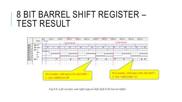
Design of 8bit barrel shifter using 21 multiplexer is successfully implemented and tested using Xilinx131 ISE This design can be expanded to larger value of bits by using the same design by introducing slight changes A barrel shifter can become stepping stone to improving computer organization and memory. When dealing with 4 variable tables, this is not a problem, but when I move to 8, I can get a single selection that has columns $0010$, $0110$, $0111$, $0101$, $0100$, $1100$, $1101$ and $1111$ selected As you can see, the bit 3 (msb) has 5 $0$ s and 3 $1$ s, bit 2 has 1 $0$ s and 7 $1$ s, bit 1 and 0 have 4 of each My questions are. The shifter provides data manipulation capabilities In Lab 6, a simple shift register that can shift by one position per clock cycle was built In this design project, a barrel shifter will be used because it has a very efficient layout and can perform nbit shifts in a single clock cycle A MUX is used to select the correct out from the ALU or.
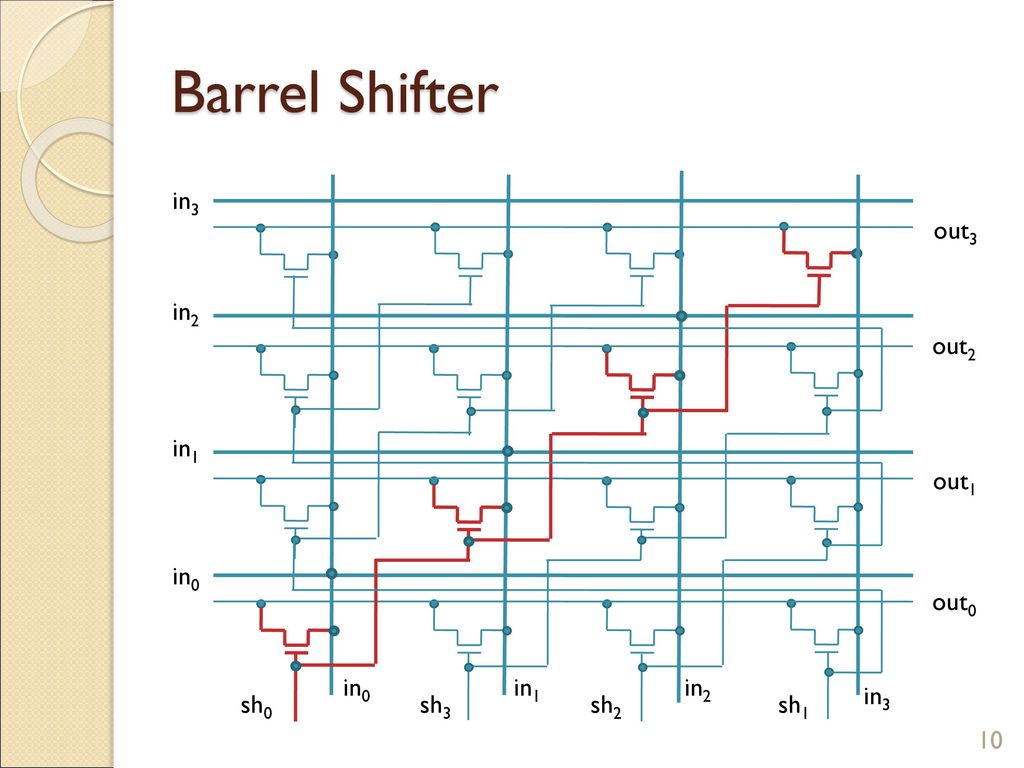
Four bit barrel shifter, where "x >> 1" denotes a shift amount greater than one adapted from Maf01 This type of Nbit shifter is well understood and easy to construct, but has space complexity of O(N 2) 3244 Support for Immediate Instructions. A Nbit Barrel Shifter can shift data left or right by N1 bits In general, a Barrel Shifter can implement arithmetic shifting, logical shifting and rotation functions 10 The signals for the input/output, and shift functions for a Nbit barrel shifter are given as follows Data In = (2x(N1)) Bit Shift Amount = (log2N) Bit. Guitar Note Detection With Shift Register Microcontrollers 4 Dec 21, F PWM on enable output of SN74HC595 shift register Digital Design 15 Jul 22, G Design of 8bit shift register Homework Help Mar 8, J Trouble Using a 74HC595 Shift Register to display numbers on 2x 7 segment displays Homework Help 3 Jan 2.
Required is n log2(n) where n is the number of bits supported So for an 8bit barrel shifter the calculation is 8 × log2(8) = 8 × 3 = 24 12 Pulsed latches Pulsedlatch circuits retain the advantages of both latches and flipflops, offering higher performance and lower power consumption within a conventional ASIC design environment. Edit, save, simulate, synthesize SystemVerilog, Verilog, VHDL and other HDLs from your web browser. • Use shift registers – Wires 121=4 – Computer sends one value at a time, one bit per clock cycle C d0 d1 d2 d3 e i0 i0 i1 i2 i3 a0 a1 load i1 2⋅4 F r om t h e c a r ' s c e n t r a l c ompu t e r 8 8 8 8 8 d D 8 xy s1 s0 8bit 4⋅1 To t h e a b o v e mi r r or di s p l a y load load load load reg0 reg1 reg2 reg3 T A I M 1 1 w i r e.
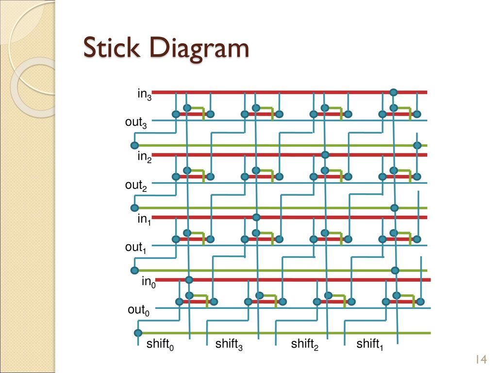
This sequential device loads the data present on its inputs and then moves or “shifts” it to its output once every clock cycle, hence the name Shift Register A shift register basically consists of several single bit “DType Data Latches”, one for each data bit, either a logic “0” or a “1”, connected together in a serial type daisychain arrangement so that the output from one. 4bit Barrel Shifter Layout Buffer Sh0 Sh1 Sh2 Sh3 A 3 A 2 A 1 A 0 Width barrel ~ O(N) Delay ~ 1 fet N diff caps Width barrel Only one Sh# active at a time l!Sh 1!Sh 0!Sh 1 Sh 0 Sh 1!Sh 0 Sh 1 Sh 0 Sp12 CMPEN 411 L21 S8 Logarithmic Shifter Structure. A multifunction high speed barrel shifter comprising three functional levels The first level performs 1/4 word shifts by a selectable amount The second level performs 1/8 word shifts on the portion of the word to be shifted and, where desired, fills the remainder of its output with fill bits The third level performs 1/32 of a data word shift.
8bit — 8 * log2(8) = 8 * 3 = 24 Basically, a barrel shifter works to shift data by incremental stages which avoids extra clocks to the register and reduces the time spent shifting or rotating data (t he specified number of bits are moved/shifted/rotated the desired number of bit positions in a single clock cycle). OR is 1 if one or both of its inputs are 1, otherwise it's 0;. VHDL Code for 8bit Barrel Shifter Sr No Name of the Pin Direction Width Description 1 d_in Input 8 data input Verilog Code for Sequence Detector "".
NOT is 1 only if its input is 0, otherwise it's 0;. Table 11 Truth table of conventional and reversible XOR gates 2 Table 21 Operations on an 8 bit barrel shifter with 3 bit shift value 11 Table 31 Operations on (n,k) reversible universal right shifter 21 Table 32 Operations on (8,3) reversible universal right shifter 24 Table 33 Operations on (n,k) reversible bidirectional logical shifter 28. Table 1 shows the truth table of a binary full adder A and B are the adder inputs,Ci is the carry input, S is the sum output, and Cout is the carry output Based on this truth table "Design of 8bit Ripple Carry Adder Using Constant Delay Logic".
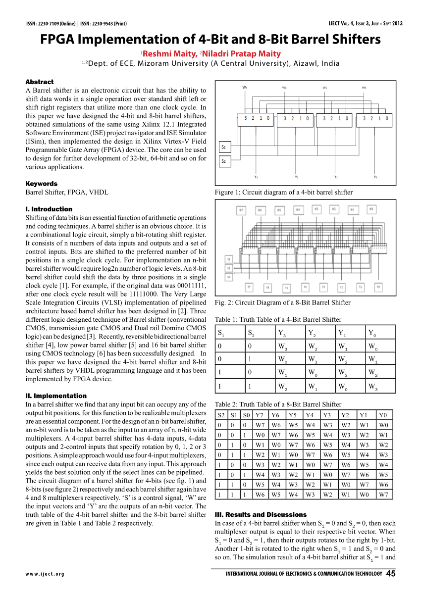
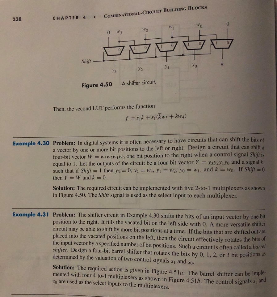
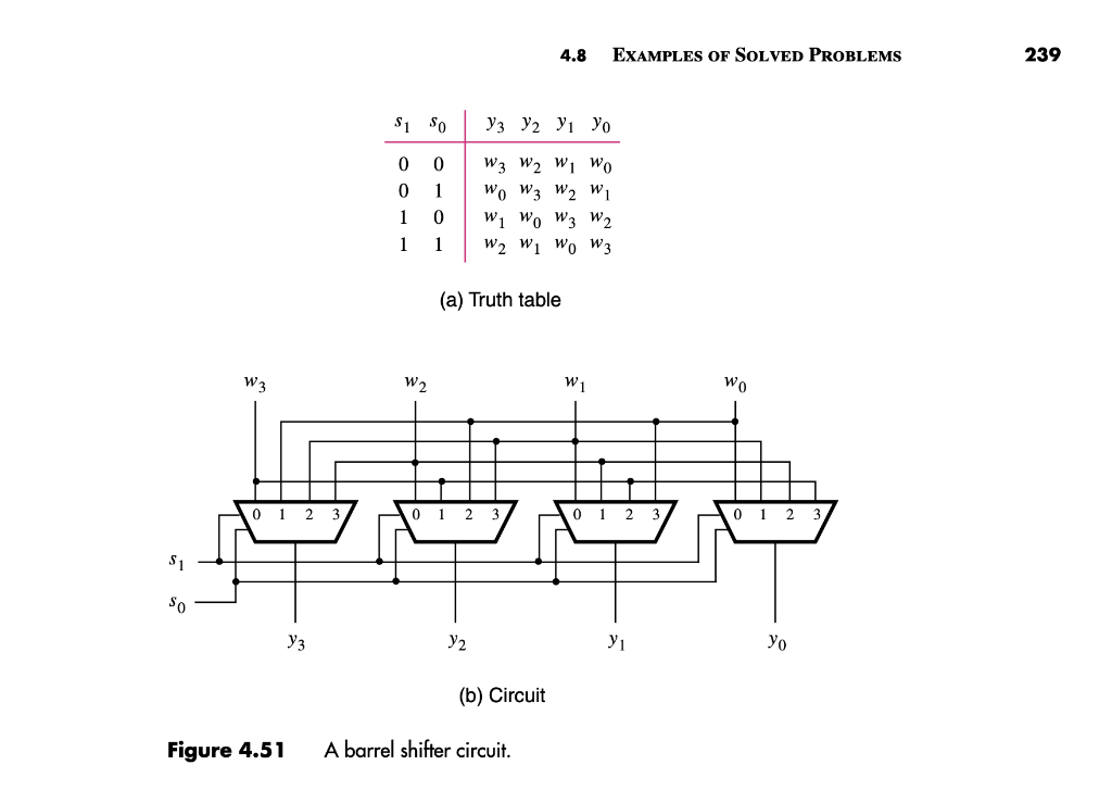
Truth table of the 4bit barrel shifter and the 8bit barrel shifter are given in T able 1 and T able 2 respectively Figure 1 Circuit diagram of a 4bit barrel shifter. A barrel shifter is a digital circuit that can shift a data word by a specified number of bits without the use of any sequential logic, only pure combinational logic, ie it inherently provides a binary operationIt can however in theory also be used to implement unary operations, such as logical shift left, in cases where limited by a fixed amount (eg for address generation unit), by a. These can often be best shown as truth tables.
Graph1Power analysis of 8bit barrel shifter CONCLUSION In this Paper, the barrel shifter is designed using complex logic structures and area of barrel shifter is reduced By using Tanner EDA 132 tool power consumed by the each logic on 250nm and 180nm is calculated and the reduced area and power barrel shifter is proposed. Four bit barrel shifter, where "x >> 1" denotes a shift amount greater than one adapted from Maf01 This type of Nbit shifter is well understood and easy to construct, but has space complexity of O(N 2) 3244 Support for Immediate Instructions. The VHDL Code for fulladder circuit adds three onebit binary numbers (A B Cin) and outputs two onebit binary numbers, a sum (S) and a carry (Cout) Truth Table describes the functionality of full adder sum(S) output is High when odd number of inputs are High Cout is High, when two or more inputs are High.
An 8bit priority encoder This circuit basically converts a onehot encoding into a binary representation If input n is active, all lower inputs (n1 0) are ignored Please read the description of the 42 encoder for an explanation. A Nbit Barrel Shifter can shift data left or right by N1 bits In general, a Barrel Shifter can implement arithmetic shifting, logical shifting and rotation functions 10 The signals for the input/output, and shift functions for a Nbit barrel shifter are given as follows Data In = (2x(N1)) Bit Shift Amount = (log2N) Bit. Bitwise operators are operators that work on multibit values, but conceptually one bit at a time AND is 1 only if both of its inputs are 1, otherwise it's 0;.
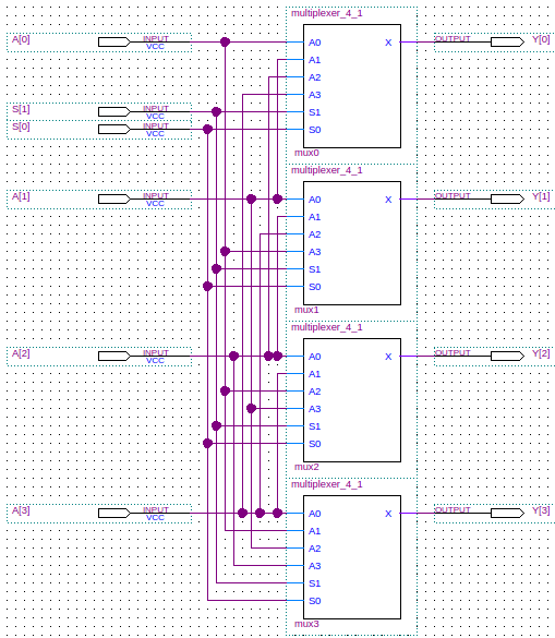
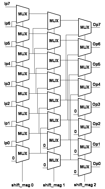
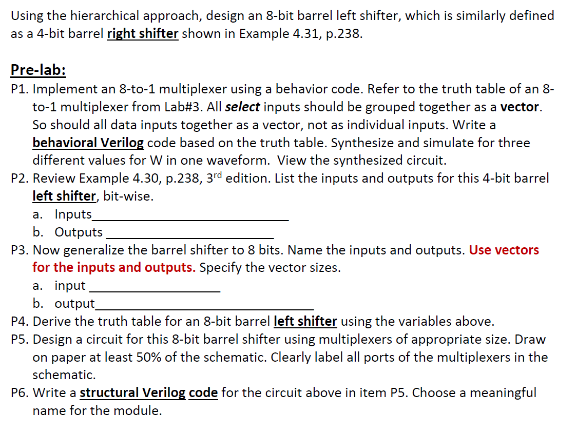
VHDL Code for 8bit Barrel Shifter Sr No Name of the Pin Direction Width Description 1 d_in Input 8 data input Verilog Code for Sequence Detector "". A multifunction high speed barrel shifter comprising three functional levels The first level performs 1/4 word shifts by a selectable amount The second level performs 1/8 word shifts on the portion of the word to be shifted and, where desired, fills the remainder of its output with fill bits The third level performs 1/32 of a data word shift. Design a circuit for this 8bit barrel shifter using multiplexers of appropriate size Draw on paper at least 50% of the schematic Clearly label all ports of the multiplexers in the schematic.
VHDL Code for 8bit Barrel Shifter Sr No Name of the Pin Direction Width Description 1 d_in Input 8 data input Verilog Code for Sequence Detector "". Barrel shifter design, optimization, and analysis (02) Barrel shifter design, optimization, and analysis. Creación y simulación de un Barrel Shifter de 8 bits, utilizando la herramienta ISE 144Build and simulation of a Barrel Shifter 8 bits, using ISE 144.
Analog electronics, Amplifier, Feedback amplifiers, Topology, VLSI Design, VHDL. " 4 bit rotate value (015) is multiplied by two to give range 030 in steps of 2 " Rule to remember is “8bits rotated right by an even number of bit positions” 11 8 7 0 immed_8 Shifter ROR rot x2 0xFF MOV r0, #0xFF,8 Reasons for constraints on Immediate Addressing 40. Table 1 shows the truth table of a binary full adder A and B are the adder inputs,Ci is the carry input, S is the sum output, and Cout is the carry output Based on this truth table "Design of 8bit Ripple Carry Adder Using Constant Delay Logic".
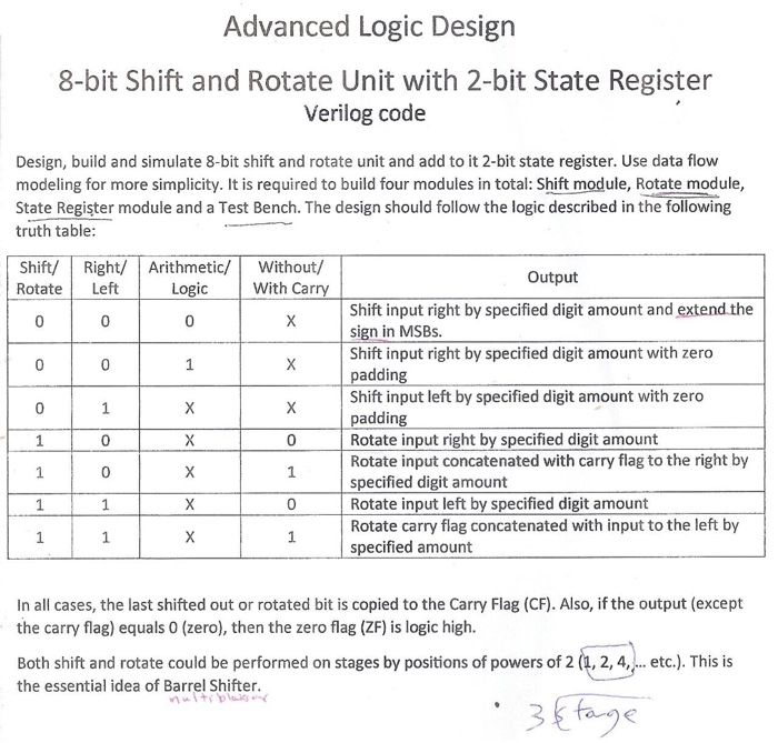
2 Derive the truth table for an 8bit barrel left shifter using the variables above;. Barrel shifter design is for natural size like (2,4,16)This project is done on 8 bit barrel shifter which can Shift input by 0,1,2,3,4,5,6,7, bit Four select lines are used as it is 8 bit barrel shifter ie S0, S1, S3 Basically barrel shifter is used with logical left shift operation which is controlled by select inputs. Parallelism were analyzed to minimize the number of execution cycles needed for 8 bit integer arithmetic operations In addition to the arithmetic unit, an optimized SRAM memory cell was designed to be used as cache memory and as fast Look Up Table The ALU consists of stand alone units for bit parallel computation of basic.
Or you can use the 16bit one level CLA adder, connecting them by CLA, as shown below To design a 64bit adder with three levels of CLA, we can use the 16bit two level CLA adder given in (b), connecting 4 16bit two level CLA adders with single level CLA generator, giving us the final implementation below Problem 3 Question. A recirculating barrel shifter allows for shifting of bits in a wrap around fashion so the lowest order bit is adjacent the highest order bit The barrel shifter 65 selects a segment comprising a 1bit, 5bit, or 8bit data segment from its input and provides this data segment in the least significant bit (LSB) positions of its output. XOR is 1 only if exactly one of its inputs are 1, otherwise it's 0;.
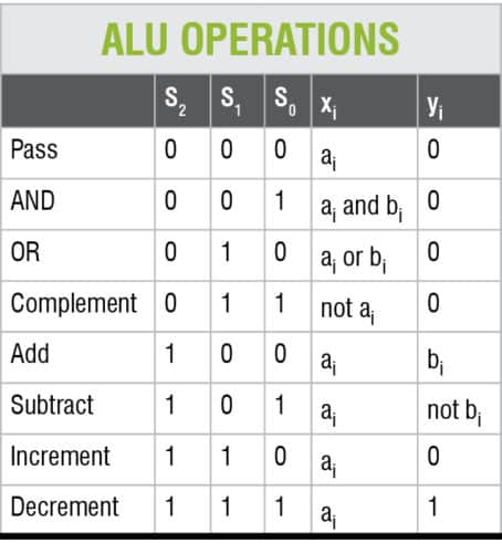
When dealing with 4 variable tables, this is not a problem, but when I move to 8, I can get a single selection that has columns $0010$, $0110$, $0111$, $0101$, $0100$, $1100$, $1101$ and $1111$ selected As you can see, the bit 3 (msb) has 5 $0$ s and 3 $1$ s, bit 2 has 1 $0$ s and 7 $1$ s, bit 1 and 0 have 4 of each My questions are. Fast 8 bit by 8 bit multiplier with an output of 16 bits, focused on speed By focusing on speed, the delay time is intended to be reduced, while the area and power consumption of the device are expected to be focused less on By speci cations provided for the project, the multiplier must accept 8 bit signed inputs and output a 16 bit resultant. 1 1 1 0 A*B (only low 8 bits used) 1 1 1 1 A>>B (logical shift) The logical operations are bitwise, meaning that for S=”0001”, O(1) is equal to A(1) AND B(1) This of course means that they ignore what sign A and B have For arithmetic operations, the ALU should truncate at 8 bits.
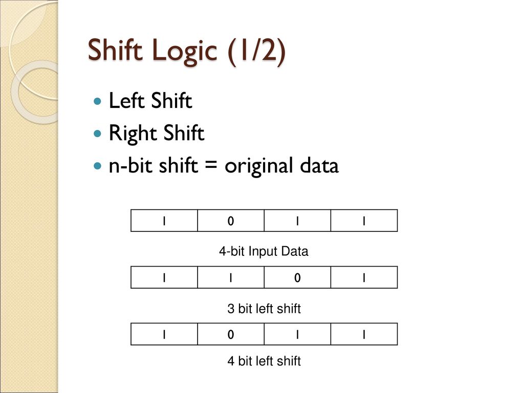
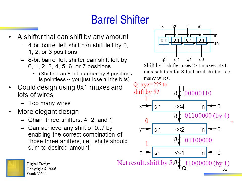
In a barrel shifter, the bits are shifted the desired number of bit positions in a single clock cycle For example, an eightbit barrel shifter could shift the data by two positions in a single clock cycle If the original data was , one clock cycle later the result will be.

Figure 15 From Vlsi Design Of Low Power Reversible 8 Bit Barrel Shifter Semantic Scholar

Vlsi Design Of Low Power Reversible 8 Bit Barrel Shifter Pdf Document

Modified Booth
Verilog For Beginners Barrel Shifter
Barrel Shifter
Vlsi Presentation 4 Bit Shifter Ppt Download
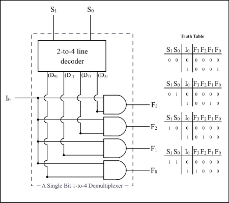
Multiplexer Wikipedia
Vlsi Presentation 4 Bit Shifter Ppt Download
Homework 4 With Solutions Homework Eecs 31 Cse 31 Ics 151 Daniel D Gajski S Web Site
More Combinational Circuits
Vlsi Presentation 4 Bit Shifter Ppt Download
Organization Of Computer Systems Computer Arithmetic

Table I From Vlsi Design Of Low Power Reversible 8 Bit Barrel Shifter Semantic Scholar
Barrel Shifter
Simplis Parts Shift Register Multi Bit

Memristive Computational Memory Using Memristor Overwrite Logic Mol
Design And Implementation Microprocessor Data Path

Dave S Hacks December 15

Design Of Low Power Barrel Shifter Using Pulsed Latches
Organization Of Computer Systems Computer Arithmetic
More Combinational Circuits

16 Bit Barrel Shifter A Mini Project Report Ppt Download

Fpga Implementation Of High Speed 8 Bit Vedic Multiplier Using Barrel

Epa1 Barrel Shifter Google Patents

Showch05

Figure 15 From Vlsi Design Of Low Power Reversible 8 Bit Barrel Shifter Semantic Scholar

Epb1 Barrel Shifter Google Patents

Shifters An Overview Sciencedirect Topics
Chapter 4 Datapath Components Ppt Download

Arithmetic Logic Unit An Overview Sciencedirect Topics

Unit 4 Dica

I Want To Resolve This Issue By Verilog Code Chegg Com

Epa1 Barrel Shifter Google Patents
Thirty Two Bit Bit Slice Patent
Using The Hierarchical Approach Design An 8 Bit B Chegg Com
Lecture 2

Epa1 Barrel Shifter Google Patents
Pdf Fpga Implementation Of 4 Bit And 8 Bit Barrel Shifters

Arithmetic Logic Unit An Overview Sciencedirect Topics
16 Bit Barrel Shifter A Mini Project Report Ppt Download

Design Of Low Power Barrel Shifter Using Pulsed Latches
Using The Hierarchical Approach Design An 8 Bit B Chegg Com
Homework 4 With Solutions Homework Eecs 31 Cse 31 Ics 151 Daniel D Gajski S Web Site
22c 60 Notes Chapter 8
Lecture 2
4 Bit Shift Register
Digital Logic And Verilog
Fpga Implementation Of High Speed 8 Bit Vedic Multiplier Using Barrel

8 Bit Barrel Shifter Verilog Code Verilog Code Of Barrel Shifter
Homework 4 With Solutions Homework Eecs 31 Cse 31 Ics 151 Daniel D Gajski S Web Site

Epa1 Barrel Shifter Google Patents
Solved Design An 8 Bit Barrel Shifter Using Multiplexers Chegg Com
Solved Just Solved Only In Verilog Code Module Bot Chegg Com

Using The Hierarchical Approach Design An 8 Bit B Chegg Com
More Combinational Circuits
Organization Of Computer Systems Computer Arithmetic
Barrel Shifter Wikipedia


